Gone to Bodie
By Carver Mead & Barbara Smith
Reprinted from "Crown Jewels of the Wire", November 2005, page 30
From an engineering perspective, a mine is simply a machine for turning
energy into Gold. The energy has to come from somewhere. In the earliest days of
the Gold rush, human muscle supplied the energy to dig gravel and slosh pans. As
the easy Gold was worked out, water-power was used to wash away hillsides and
operate sluice boxes. But the really valuable gold deposits were in Quartz veins
that ran underground - the "Mother Lode."
Energy was required to lift
the ore from underground and pound it into fine dust so the Gold could be
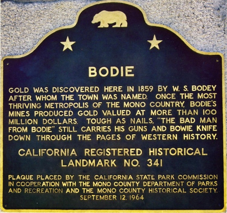
removed. The Bodie deposits were found in a desert area at 8300 ft. elevation,
where winter temperatures were 30 degrees below zero. Firewood was transported
many miles on muleback from forests near Mono Lake. The wood was burned for
heat, and to run steam engines that supplied energy to the mines and mills. But
the forests were not limitless, and wood became increasingly scarce and
expensive.
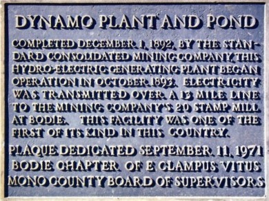
The Standard Consolidated Mine was the largest operation in Bodie. Its
20-stamp mill was powered by a steam engine that required 7 cords of firewood
each day. By 1892, wood was so scarce that its high price materially affected
the profitability of the entire operation. Thomas H. Leggett, superintendent of
the mill, had followed recent electrical developments and was convinced that
hydroelectric power, generated in the Sierra foothills 13 miles away, could be
economically transmitted to the mine. He convinced the mine owners, and the
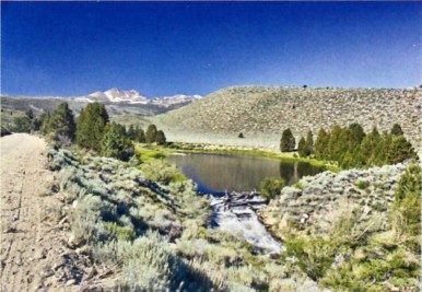
project was undertaken. An earth-filled dam was constructed across Green Creek
to form Dynamo Pond. An earth ditch cut into the hillside carried the water
nearly a mile to a point 355 ft. above the power plant. The plant itself
contained a single Westinghouse generator driven by two 21-inch Pelton water
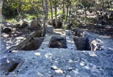
wheels. The dam has long since been breached, but the major part of it still
stands, and can be seen in the photo below. The roadway to the left follows the
course of the old ditch. All that remains of the power plant is the foundation
and some sheet metal. The wheel pits are clearly visible.
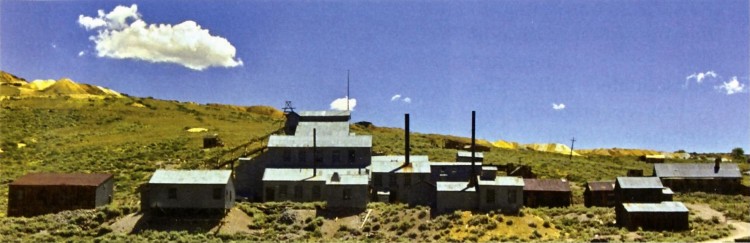
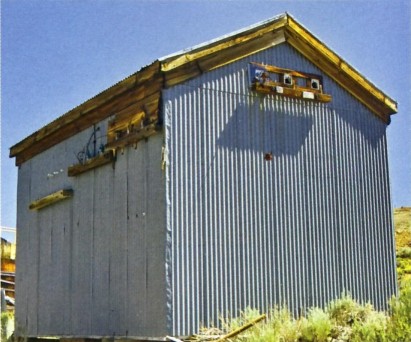
Power was transmitted to this transformer house at the Standard Consolidated
mill. The system was originally single-phase, but was upgraded to three-phase at
a later date, for which we found evidence on the line as well.
160 horsepower
was transmitted 13 miles at 3.3kV. We are fortunate to locate an article by
Leggett that describes the project in great detail (Transactions of the American
Institute of Mining Engineers, vol. 24, p. 315, 1894). That paper contains the
line map shown below.
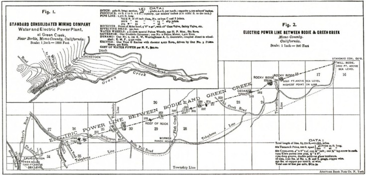
The map also contains a quite complete synopsis of the plant and line
specifications, and a parts list of the line material used. It is accompanied by
the following description: The line crosses extremely rough country, not 500
yards of which is level beyond the town-limits. Most of the ground is very
rocky, over 500 pounds of dynamite being used in blasting the pole-holes.
All the Bodie books that mention the line have the following comment: The poles
were installed in a straight line, as it was feared that the electricity
would not be able to turn comers. There is no indication in the article that any
such misconception was held by Leggett or his engineers. In fact, the line runs
over some steep ridges that cause abrupt changes in direction of the wires
vertically. So the statement shows the ignorance of the writer rather than that
of the line builders.
|
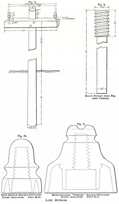
The article also contains the drawing at right showing all the details of the
pole construction, accompanied by the following description:
The wire is of No.1 (B. & S.) gauge, soft-drawn bare copper, and is
attached to standard double-petticoat deep-groove glass insulators, Fig. 10,
carried an Klein patent iron pins, Fig. 9...
The line crosses a number of
very steep ridges (from 300-800 feet in height) and on these the wire necessarily
pulls heavily an the top pole, and especially on its pins and insulators. In all such places the
ordinary double-petticoat insulators were
replaced by the large "Pomona" insulator, Fig. 11, on which the
wire is carried in a groove across the top, and its weight is therefore
directly down upon, and in line with the center of, the pin.
|
 |
Of course the possibility of finding even a piece of a Pomona excites us
greatly. We know where to look: they would have been used on the pole sites atop
the steepest ridges, all of which were indicated on the map. We also want to
ascertain when the line had been converted to three-phase, and to what extent
the original pole structure had been preserved until the line was wrecked.
So off to the line we go, starting west from Bodie toward the highest point
on the line. Within an hour we locate pole stubs heading in the right direction.
Most of them are stripped completely bare: not a tie-wire, bolt, pin, or shard of
glass. Too close to town; let's press on. The route gets rougher as we gain
altitude; maybe we'll get lucky.
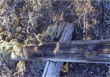
Here is a crossarm in pretty good shape, and it has two bolt heads in it.
Let's turn it over and see how they did it.
The poles are of round tamarack timber, 21 feet long, 6 inches in diameter at the top, set 4 feet in the
ground; poles 25 feet long being used
through the town, and along the line wherever there is danger of deep snow-drifts. They are placed 100 feet apart, and fitted each with a 4-
by 6-inch cross-arm, boxed into the pole, and held by one bolt and one
lag-screw.
Sure enough, this is an original arm - wow! We have never seen the
one-bolt-one-Iag-screw combination on any other power line, so this is a great
start. A few pole sites later we find a crossarm with the two original iron pins
still in it, but the lead threads missing. Apparently the threads had stuck in
the insulators when they were being unscrewed, and so the bare pins were left
behind.
By now the country is getting really rough, so
we expect to find more stuff. Sure enough, here is a crossarm with the
original solid-iron pin still in place, complete with lead threads. Wow! Still
as good as new after 113 years! We occasionally see a few shards of glass near
some of the pole sites, but nothing to excite an insulator collector. Exactly
what deep-groove double-petticoat insulator did they use on this line?
And where did they all go? Most lines have some whole ones left behind - what
happened here? Perhaps when they got to the ridge they would have become less
diligent about carrying all the stuff out. Barb speculates that they kept a
count of all the line material, and had to return each insulator even if it was
broken. That speculation continues to be our best guess for why we can never get
all the pieces to fit a broken insulator together - we keep climbing higher.
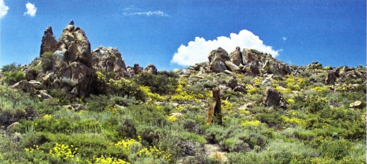
The next pole site is surrounded by the most amazing display of desert
flowers we have ever encountered. And there, 6 ft. from the stub is what looks
like a whole insulator. Hmmm, it is certainly a wide-groove double-petticoat
one, so it fits Leggett's description all right. On closer inspection, it is
split in half. Fitting the two halves together reveals its identity: a CD 162
version [100]. Its dome is embossed in an arc "W. BROOKFIELD / NEW
YORK" with "PAT. FEB 12TH 1884" on the front skirt. Not a rare
insulator by any means, but at least we know what was used on the original line.
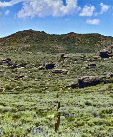
We are not far from the ridge by now, and our excitement grows as we climb.
This is the highest point on the line. It is very steep on both sides, and will
certainly be a pole site that originally used Pomona insulators. As we break
over the ridge we are greeted by a spectacular view of Mono Lake. Recovering
from the view, we search the site carefully. A few shards of ice-blue glass are
all that remains. Disappointing, but we have 10 more Pomona sites to find and
search. We look west across a broad valley sloping to the south. The ridge on
the other side looks as high as this one. We pull out the topo map and find our
location. We are at the place Leggett's map shows as the highest point on the line, but our elevation is
8710 ft., not 9000 ft. as Leggett indicates. Yet another puzzle to unravel. We
are a long way from the truck, and it is getting late. The broad valley and
ridge on the other side will have to wait 'til another day.
We continue to wonder about the conversion to three-phase. One day it all
becomes clear - we find a pole top that is complete and original - it could be
in service today. The arm is boxed into the pole, just as Leggett had described,
and it used one lag screw and one bolt. But they had nailed a side-pin to the
top of the pole! So that was how they supported the third wire. And the nails
are round, indicating a later origin than the square nails we found in the
crossarms.
The insulators they had used for this later addition were ice-blue
Locke CD 287.1, which bore a patent date of May 22, 1894, so they couldn't have been original on the line that was
built in 1892.
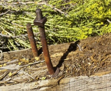
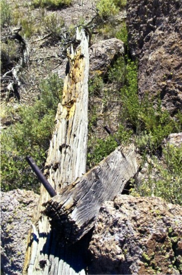
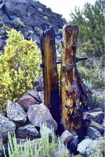
When the underground portion of a Tamarack pole rotted, a new stub of Juniper
was dug in alongside, and bolted to the standing pole with 3/4 in. steel bolts.
We are imagining the crusty old linemen, faithful mule loaded up with new stub
and tools, trudging up the rocky hillside to the site of a leaning pole. A lot of digging with bar and
shovel to get the new stub in the ground. Then he takes out his auger and bores
a hole, one turn at a time through both stub and pole. He drives the bolt all
the way through, and runs up the nut, not too tight yet. He augers one more hole
through both pole and stub, nearer the ground this time. The auger is harder to
use this close to the ground, but he moves some rocks and manages to get
through. After a bit of prying the holes line up enough to drive the second bolt
through. Once both nuts are thoroughly tightened, this pole is straight and
strong. Good job! Time for a beer at the Sawdust Corner Saloon!
Each day we find another place to intercept the line, and then begin to
search for pole stubs. We had drawn a straight line on our map from Bodie to the
Green Creek Plant. We soon realize that, contrary to all the stories, the line
is quite far from our straight line in several places. The route has been very
carefully chosen to make installation and maintenance as easy as possible.
Subtle changes in direction allow the line to run through valleys and natural
passes that make the actual route much more hospitable than a straight route. We
develop great respect for these Mining Engineers.
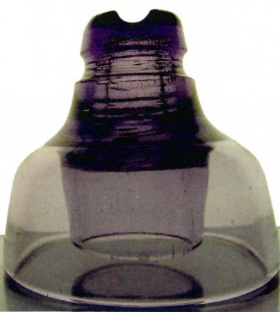
Leggett tells us that the rare CD 244 "Pomona" insulators were used
on ridges where the line dropped abruptly. These are the same units that were
used a year earlier on the San Antonio Canyon line to Pomona and San Bernardino,
CA. They were supplied by Westinghouse, and were made of "clear flint
glass." The few that have been recovered are all purple, presumably from
exposure to the sun. There are twelve sites that we identify for possible Pomona
use, most of which are shown on Leggett's map. The vast majority of the sites
along the line are completely clean, often even the bolts and nuts have been
taken away. Occasionally there is a tie wire, bolt, or shard of glass.
The Pomona sites are no exception, in spite of their more rugged
surroundings.
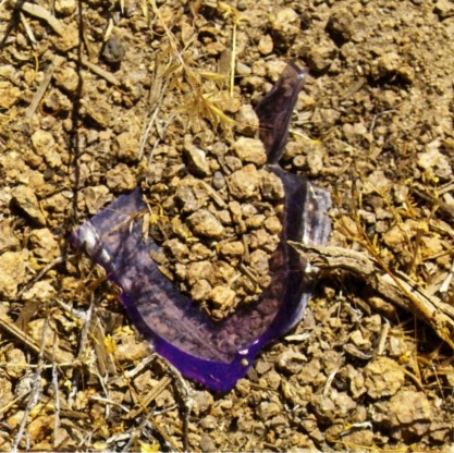
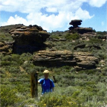
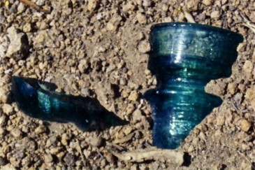
In the middle of a high, sloping valley is a rocky ridge. Barb is standing
patiently, waiting for Carver to get done taking pictures of the pole stub.
"Look at That." Sure enough, there in the dirt is a purple shard of
glass the first sign of a real Pomona insulator. The size and shape are right.
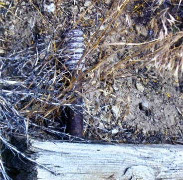
We dig the entire area, and come up with a few more small shards. The main body
of the insulator is simply not there. They took it away. Each day we get to one
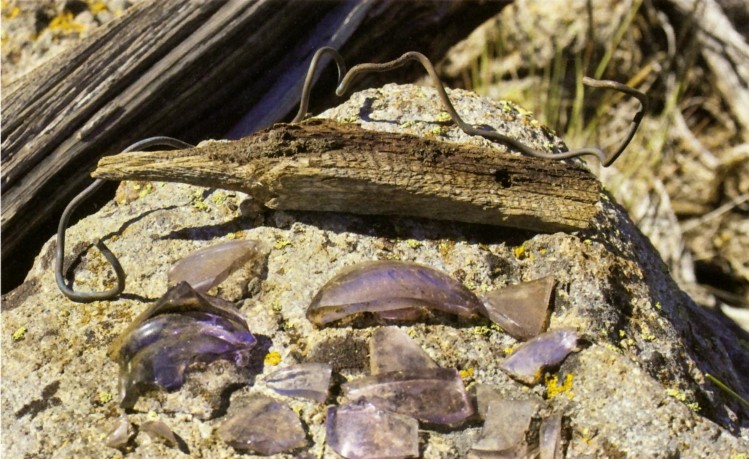
or two potential Pomona sites. By the time we have visited them all, only three
have any Pomona pieces. Of those, the most complete set of pieces we find is
shown below. Not enough to glue together, but enough to know the entire history
of this most amazing historic power project, straight out of the Wild West!
|